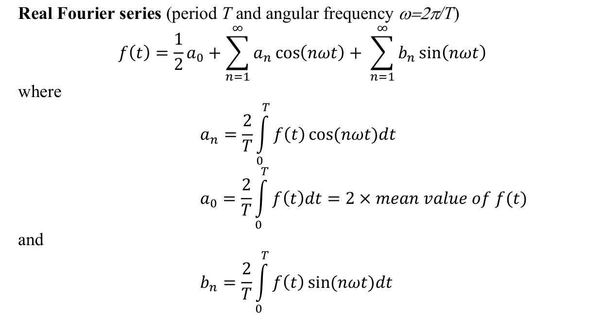
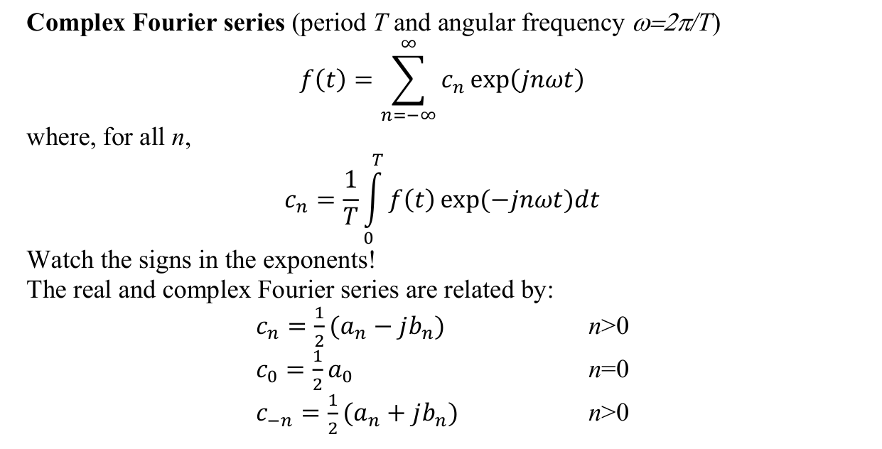
How do you know the even extension of h(t) = t is a TRIANGLE wave?
You do not recognise it, you BUILD it, in three forced moves. The question hands you only a fragment, the ramp on , and two instructions: make it EVEN, and make it PERIODIC. Each instruction fixes part of the graph with no freedom left, and what comes out at the end happens to be a zigzag.
Step 1: draw only what you are given
Step 2: “even” forces the left half, it is a mirror
Even means : whatever height the graph has at , it must have the SAME height at . So the blank left side is not a choice; it is the mirror image of the ramp, as if the page were folded along the vertical axis. The ramp rising to the right becomes a ramp falling from the left: at the height is , sliding down to at the origin.
Step 3: “periodic” forces everything else, copy the V forever
The V between and is one full period. Periodicity stamps identical copies to the left and right, end to end. Watch what happens at the seam : the V ends at height , and the next copy BEGINS at height (its own left edge). The heights match, so the copies join without any jump, and each joint becomes a sharp peak. Valleys sit at and peaks at
Why a triangle and not a curve or a staircase
Because every piece of the final graph is a copy of the original ramp, and the original ramp is a STRAIGHT LINE. Mirroring a straight line gives a straight line; repeating straight lines gives straight lines. The only shape you can build out of straight segments that alternately rise and fall is a zigzag, and a zigzag is what “triangle wave” means. If the given half-range had been instead, the same two moves would produce repeating parabola arcs (Q1(b)'s scallops), not triangles: the shape of the output is always inherited from the shape of the input fragment.
The contrast: the ODD extension of the same ramp is a sawtooth
Odd means mirror AND flip: the left half becomes continuing straight through the origin (at the height is ). Now check the seam: one period ends at height and the next begins at . The heights do NOT match, so every seam is a cliff, and the result is the jumping sawtooth. Same fragment, different symmetry instruction, completely different waveform. This seam check is also why the triangle's coefficients decay fast, like (continuous, no jumps), while the sawtooth's decay slowly, like , with Gibbs ringing at every cliff.
The recipe, reusable for any half-range question
1. Draw the given fragment on its half range.
2. Even: fold it across the vertical axis. Odd: fold and flip below the axis.
3. Copy the completed period end to end forever; check the seams for jumps.
Whatever appears is the waveform, named afterwards. Triangle was the output here, never an assumption.